


I will guide you through connecting a digital timer. This guide provides clear, step-by-step instructions. You will learn to connect it to its power supply, input signals, and output terminals. This lets you control many different devices.
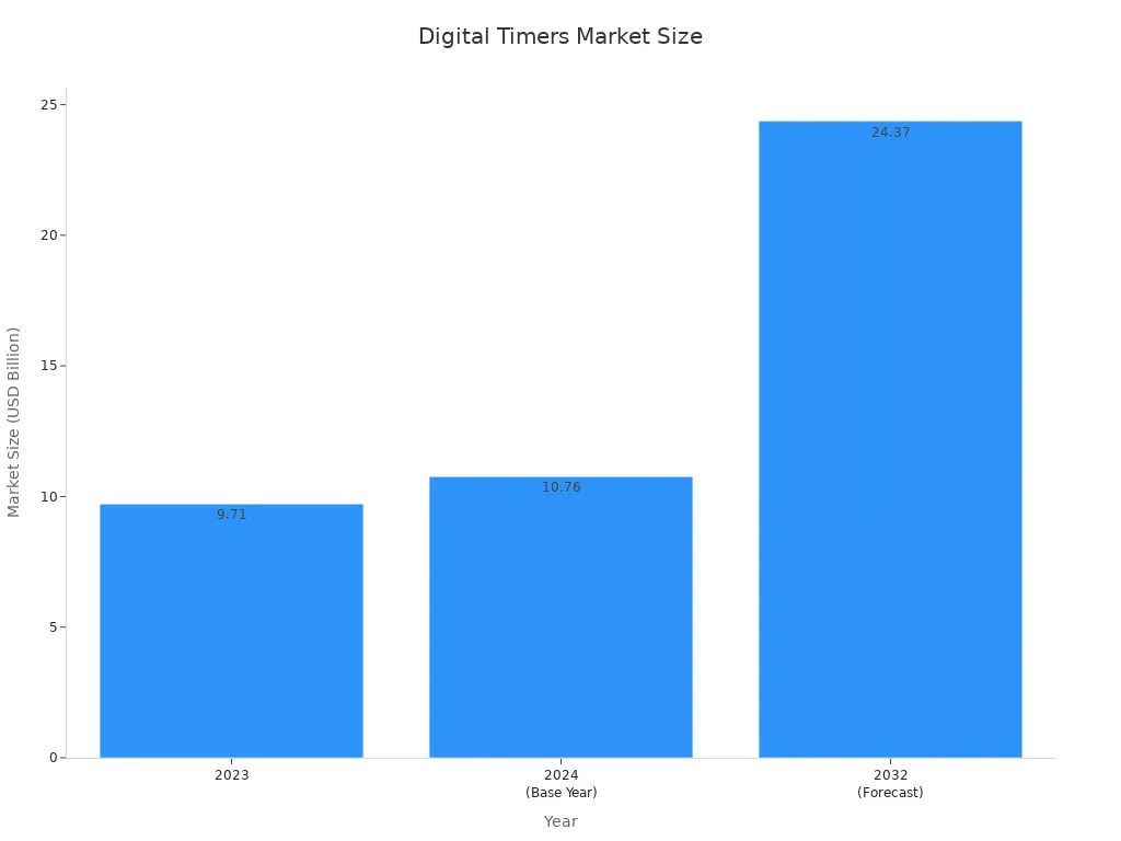
The market for digital timers is expanding rapidly. This shows how crucial these devices are becoming.
| Year | Market Size (USD Billion) |
|---|---|
| 2023 | 9.71 |
| 2024 (Base Year) | 10.76 |
| 2032 (Forecast) | 24.37 |
We will explore the essential Timer Wiring Diagram. You will also understand how to use an Industrial Digital Timer. We will cover setting up a High Precision Timing Switch and how a PLC Timer Module functions. I will also explain the Time Delay Mode for various applications.
Key Takeaways
- Understand the timer’s terminals: Power (L/N or +/-), Input (Control/Trigger), and Output (NO/NC/COM). Each terminal has a specific job.
- Always prioritize safety. Turn off power before wiring. Use insulated tools and wear safety gear like gloves and glasses.
- Connect the timer’s power first. Then, wire the device you want to control to the timer’s output terminals, usually COM and NO.
- For high-power devices, use a contactor. The timer controls the contactor, and the contactor handles the large electrical load safely.
- After wiring, test the timer. Check its display, set a simple program, and verify that connected devices turn on and off as planned.
Understanding Digital Timer Terminals and Functions
When I look at a digital timer, I see several important connection points. These are called terminals. Each terminal has a specific job. Knowing what each one does helps me wire the timer correctly.
Power Supply Terminals (L/N or +/-)
These terminals are where I connect the power to make the timer work. For AC (alternating current) power, I usually see “L” for Live and “N” for Neutral. If it’s a DC (direct current) timer, I will find “+” for positive and “-” for negative. It is important to give the timer the right power. For many standard digital timers, I see these ratings:
| Feature | Rating |
|---|---|
| Operating Voltage | 230V AC |
| Current Rating | 16A |
This means the timer needs 230 volts of AC power and can handle up to 16 amps.
Input Terminals (Control/Trigger)
Input terminals are like the timer’s ears. They listen for signals that tell the timer what to do. These signals can start, stop, or reset the timing function. I might use a push button or a sensor to send a signal. Some timers can handle different types of input signals. For example, some models support various input types:
| Model | Input Types | Supply Voltage (VDC/VAC) |
|---|---|---|
| H5CC-A11F | Gate (NPN/PNP), Reset (NPN/PNP), Signal (NPN/PNP) | 24 to 240 VDC/24 to 240 VAC |
| H5CC-A11SD | Gate (NPN/PNP), Reset (NPN/PNP), Signal (NPN/PNP) | 12 to 48 VDC/24 VAC |
| H5CC-AD | Gate (NPN/PNP), Reset (NPN/PNP), Signal (NPN/PNP) | 12 to 48 VDC/24 VAC |
Digital input terminals often work with something called “contact closure.” This is when a switch or sensor opens or closes a circuit. It tells the timer about a change. An electrical signal then shows the circuit’s state. A closed circuit means current flows, and the timer sees a ’1′. An open circuit means no current, and the timer sees a ’0′. I also use hardware triggers for external events to control data. Pulse inputs are good for counting things, like how many times a turbine flowmeter spins.
Output Terminals (NO/NC/COM)
These terminals are the timer’s hands. They control other devices. I usually see three types: NO (Normally Open), NC (Normally Closed), and COM (Common).
- COM (Common): This is the shared connection point.
- NO (Normally Open): This contact is open when the timer is off. It closes when the timer activates.
- NC (Normally Closed): This contact is closed when the timer is off. It opens when the timer activates.
I connect the device I want to control to the COM terminal and either the NO or NC terminal, depending on how I want it to work. The maximum current and voltage these outputs can switch are very important. For example, a Live Electrical Digital Timer can switch up to 20 Amps at 220V. Other models have different capacities:
| Timer Model | Max. Switching Current (Resistive) | Supply Voltage | Output Relay |
|---|---|---|---|
| TIME162D | 20Amps | 220V, 50/60Hz | 250VAC 16A Resistive |
For other models, I see these ratings:
| Timer Model | Output Contacts | Supply Voltage |
|---|---|---|
| UNI-1M | 16Amps/250V AC1 | 12-250V AC/DC |
| UNI 4M | 8Amps/250V AC1 | 12-250V AC/DC |
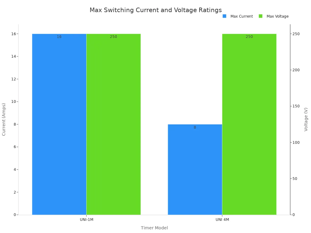
These details are crucial for choosing the right digital timer supplier.
Digital Timer Specifications and Ratings
When I choose a digital timer, I always look at its specifications and ratings. These details tell me what the timer can do and where I can use it safely. I consider these points very important for any project.
First, I check the electrical specifications. These tell me about the power the timer needs and what it can control. For example, I often see timers that need a Supply Voltage of 220V, 50/60Hz. The Output Relay might be 250VAC 16A Resistive. This means it can switch a good amount of power. I also note the Power Consumption, which could be around 10VA. If I plan to control lights, I check the Incandescent/Halogen Lamp Load 230V, which might be 2600W. The Minimum Switching Time is usually 1 second, and the Time Accuracy at 25°C is typically ±1s/day (quartz).
I also pay close attention to the load ratings. Many timers have a 16A load rating. This is good for general use. Some even have a 16A load rating for immersion heaters. If I am controlling LED lights, I look for the 100W LED rating.
Environmental ratings are also key. They tell me where the timer can operate without problems. I see an Operating Temperature range of -5°C to 45°C (23°F to 113°F). For storage, the Storage Temperature is -10°C to 55°C (14°F to 131°F). I also check the Markings. Many timers are CE marked. This means they meet EN61010-1:2010 low voltage and EN61326-1:2013 EMC directives. The Ambient Operating Temperature is often -10°C to + 50°C. The Protection Class is usually Class II According to EN 60730-. The Ingress Protection is IP20. Finally, I confirm the Approvals, like CE. These details help me find the right digital timer supplier for my needs.
| Rating | Value |
|---|---|
| Operating Temperature | -5°C to 45°C (23°F to 113°F) |
| Storage Temperature | -10°C to 55°C (14°F to 131°F) |
| Markings | CE marked (meets EN61010-1:2010 low voltage and EN61326-1:2013 EMC directives) |
| Ingress Protection | IP20 |
| Approvals | CE |
| Protection Class | Class II According to EN 60730- |
Essential Safety Precautions for Timer Wiring
Wiring a digital timer involves electricity. I always prioritize safety. Following these precautions helps me avoid accidents and ensures a successful installation.
Disconnecting Power Before Wiring
I always start by turning off the power. This is the most important safety step. I go to the main electrical panel and switch off the circuit breaker that controls the area where I will work. I do not just rely on a wall switch. After turning off the breaker, I use a voltage tester. I check all wires I plan to touch. This confirms no electricity flows through them. I want to be absolutely sure the power is off. This protects me from electric shock.
Required Wiring Tools and Equipment
I gather all my tools before I begin. Having the right equipment makes the job easier and safer. I always use insulated screwdrivers. These screwdrivers have handles that protect me from electricity. I also need wire strippers. They help me remove wire insulation cleanly without damaging the copper inside. A multimeter is useful. I use it to check voltage and continuity. Safety glasses protect my eyes from stray wire pieces. Work gloves offer an extra layer of protection for my hands. I make sure all my tools are in good condition.
Consulting the Digital Timer Manual
Every digital timer comes with a manual. I always read it carefully. The manual provides specific instructions for my particular timer model. It shows me the exact wiring diagrams. It also lists the correct voltage and current ratings. I learn how to program the timer from the manual. It often includes troubleshooting tips. Following the manufacturer’s guidelines is crucial. It ensures I wire the timer correctly and safely. This also helps me understand the timer’s full capabilities. When I choose a digital timer, I also consider the reputation of the digital timer supplier. A good supplier provides clear, comprehensive manuals.
Personal Protective Equipment (PPE)
I always make sure to wear the right personal protective equipment (PPE) when I work with electricity. This equipment is my last line of defense against injury. It helps keep me safe from electrical shocks, burns, and other hazards. I never skip this step.
First, I always put on insulated gloves. These gloves are special. They have a thick rubber layer that stops electricity from passing through to my hands. I check them for any tears or holes before I use them. My hands are very important, and these gloves protect them.
Next, I wear safety glasses. My eyes are also very important. When I cut wires, small pieces can fly off. Safety glasses shield my eyes from these flying debris. They also protect against accidental sparks. I make sure my glasses fit well and do not fog up.
I also pay attention to my footwear. I choose non-conductive shoes or boots. These shoes have rubber soles. They help insulate me from the ground. This is important because electricity always tries to find the easiest path to the ground. My shoes help break that path.
Finally, I wear appropriate clothing. I avoid loose clothing that could get caught in wires or tools. Sometimes, I wear long sleeves and pants made from natural fibers. These materials are less likely to melt onto my skin if there is a flash. I also make sure my work area is clear. I do not want anything to trip over. Using the right PPE is a simple way to stay safe. It is a habit I always follow. When I buy new equipment, I look for a reliable industrial digital timer supplier who also offers safety advice.
Basic Digital Timer Wiring Diagram for ON/OFF Loads
I want to show you how to wire a digital timer for simple ON/OFF control. This is a common setup. It lets you turn devices on and off at set times. I will guide you through each step.
Identifying Live, Neutral, and Load Wires
Before I connect anything, I need to know my wires. Every electrical circuit has three main types of wires.
- Live Wire: This wire carries the electrical current from the power source. It is the “hot” wire. It brings power to the timer and the device.
- Neutral Wire: This wire completes the circuit. It carries the current back to the power source.
- Load Wire: This wire connects the timer’s output to the device you want to control. This device is called the “load.”
Wire colors can change based on where you live. I always check the local standards. Here are some common color codes I see:
| System/Wire Type | Live | Neutral | Ground |
|---|---|---|---|
| Modern UK | Brown | Blue | Green/Yellow |
| Old UK | Red | Black | Green |
| USA (NEC) | Black or Red | White | Green or Bare Copper |
Knowing these colors helps me identify each wire correctly. This is a critical first step for any Timer Wiring Diagram.
Connecting Power to the Digital Timer
Now, I connect the main power to the digital timer. This gives the timer the electricity it needs to work.
- Locate Power Terminals: I find the “L” (Live) and “N” (Neutral) terminals on my digital timer. If it is a DC timer, I look for “+” and “-”.
- Connect Live Wire: I take the live wire from my power source. I connect it to the “L” terminal on the timer.
- Connect Neutral Wire: I take the neutral wire from my power source. I connect it to the “N” terminal on the timer.
This step powers the timer itself. It makes the display light up and allows me to program it. I always double-check these connections. A secure connection prevents problems. If you are looking for reliable components for your projects, consider an industrial timer solutions provider.
Wiring the Load to the Timer’s Output
Next, I connect the device I want to control (the load) to the timer’s output. This is where the timer actually switches the power to your device.
- Identify Output Terminals: I find the COM (Common), NO (Normally Open), and NC (Normally Closed) terminals on the timer. For most ON/OFF applications, I use COM and NO.
- Connect Live to COM: I take a short piece of live wire. I connect one end to the “L” terminal where I connected the main live wire. I connect the other end to the “COM” terminal on the timer’s output. This brings live power to the switch part of the timer.
- Connect Load to NO: I take the live wire that goes to my device (the load). I connect this wire to the “NO” (Normally Open) terminal on the timer.
- Connect Load Neutral: I connect the neutral wire from my device directly to the main neutral wire. It does not go through the timer’s output terminals.
Here is an important point, especially for lighting circuits:
- Many electrical timers need a neutral wire. This powers the timer’s internal clock. It does this without sending power to the load.
- If a switch only has two wires and an earth wire, it means it is a switched live setup. There is no neutral wire available at the switch.
- In homes without a neutral wire at the switch, installing timer switches can be difficult. This is a common issue in the UK.
- A neutral wire provides power to the light switch timer for its internal clock.
- If only two wires are present at the switch, it is a switched live circuit. A neutral wire is needed to correctly power the device.
- The simplest solution for wiring a timer switch with no neutral wire is to buy a battery-powered timer. This type does not need a neutral connection.
- For example, some no-neutral timers use two AA batteries. They power themselves and mechanically switch the lights on and off. They fit over an existing wall light switch.
For a standard setup, the N/O (Normally Open) terminal is for the switched live connection to the load. A typical setup for such a timer at the switch involves three connections: Permanent Live, Neutral, and Switched Live. The switched live comes from the N/O connection of the switch. The Neutral connection also connects to the load. This completes the Timer Wiring Diagram for basic ON/OFF control. If you need to buy many timers, look for an electrical timer wholesale supplier.
Advanced Digital Timer Wiring Diagram Applications
I often find that basic ON/OFF scheduling is not enough for all my projects. Sometimes, I need more control. This is where advanced digital timer wiring comes in handy. It lets me connect other devices to trigger or control the timer’s functions.
Wiring with a Separate Control Input (e.g., Push Button)
Imagine I want to start a process with a simple push of a button, but I also want the timer to manage how long it runs. This is a perfect use for a separate control input. Instead of just relying on a pre-set schedule, I can use an external signal to tell the timer when to begin its countdown or sequence. For example, I might use a push button to activate a fan for a specific duration, or a sensor to start a pump when a certain condition is met. This gives me much more flexibility in how I automate tasks.
Understanding Input Signal Types (Dry Contact vs. Voltage)
When I connect an external device to my digital timer, I need to understand the type of signal it sends. There are two main types of input signals: dry contact and voltage input. I see these differences often:
| Feature | Dry Contact Signal | Voltage Input Signal |
|---|---|---|
| Nature | Passive, no external power | Active, requires external voltage |
| Operation | Closes a circuit to indicate a state | Applies a specific voltage level |
| Power Source | Timer provides internal wetting voltage | External power supply provides voltage |
| Wiring | Two wires, simple connection | Two wires, polarity sensitive |
| Isolation | Inherently isolated | Requires careful consideration for isolation |
| Noise Immunity | Generally good due to simple on/off | Can be susceptible to electrical noise |
| Applications | Simple switches, pushbuttons, relay contacts | Sensors, PLCs, control systems |
| Cost | Often lower due to simpler components | Can be higher due to power supply requirements |
Let me explain these in simpler terms:
- Dry Contact Signal:
- This is a passive signal. It does not make its own power.
- It works like a simple light switch. It either closes (turns on) or opens (turns off) a circuit.
- The timer usually gives a small internal voltage to sense when the contact closes.
- I use it with simple things like pushbuttons, limit switches, or relay contacts.
- Voltage Input Signal:
- This is an active signal. It uses an external voltage.
- The timer looks for this voltage to be present or absent. It might also look for a specific voltage level.
- It needs an outside power source to create the voltage signal.
- I often use it with sensors, PLCs (Programmable Logic Controllers), and other electronic control devices.
Understanding these differences helps me choose the right programmable timer module for my needs and wire it correctly.
Connecting the Control Input to the Digital Timer
Connecting the control input to the digital timer is a straightforward process once I know the signal type.
For a dry contact input, I typically connect two wires from the external device (like a push button) to the timer’s input terminals. These terminals might be labeled “IN,” “S1,” or “Trigger.” Since it is a dry contact, there is no specific polarity to worry about. I just make sure the connection is secure. When the button is pressed, it closes the circuit, and the timer senses this change.
For a voltage input signal, I connect the two wires from the external device (like a sensor) to the timer’s input terminals. With voltage inputs, polarity is often important. I make sure to connect the positive (+) wire from the sensor to the positive input terminal on the timer, and the negative (-) wire to the negative input terminal. If I connect them backward, the timer might not detect the signal, or it could even damage the timer or the sensor. I always check the timer’s manual for the exact terminal labels and any specific wiring instructions for voltage inputs. This ensures my Timer Wiring Diagram is correct and safe.
Wiring a Digital Timer to Control a Contactor or Relay
Sometimes, I need my digital timer to control something that uses a lot of electricity. Think about big motors, powerful heaters, or many lights at once. My timer’s internal switch might not be strong enough to handle all that power directly. This is where a contactor or a relay comes in. I use the timer to switch a small amount of power. This small power then turns on a much bigger switch, which is the contactor or relay. It is like using a small finger to push a big button. The big button then turns on the heavy machinery. This method keeps my timer safe and lets it control much larger loads.
Why Use a Contactor for High-Current Loads
I often get asked why I cannot just connect a high-power device directly to the timer. Here is why: most digital timers have a built-in relay. This relay is like a small switch inside the timer. It can only handle a certain amount of current, usually around 10 to 16 amps. If I try to connect a device that pulls more current than that, the timer’s internal relay will get too hot. It can burn out or even cause a fire.
A contactor is a heavy-duty electrical switch. It is designed to handle very large currents, sometimes hundreds of amps. It has strong contacts that can safely switch power to big motors, industrial heaters, or large lighting systems. The contactor itself needs a small amount of power to turn on. This small power comes from my digital timer. So, the timer switches the contactor on or off, and the contactor then switches the high-current device on or off. This setup protects my timer and ensures the high-power device operates safely. It is a smart way to manage heavy electrical loads.
Connecting Timer Output to Contactor Coil
Now, I will show you how to connect the timer to the contactor. This is a key part of the overall Timer Wiring Diagram for high-power applications.
- Identify Contactor Coil Terminals: First, I look at my contactor. It will have two terminals for its coil. These are usually labeled A1 and A2. This coil is what makes the contactor switch on when it gets power.
- Connect Timer’s COM to Live: I take a short wire. I connect one end to the “L” (Live) terminal where my main power comes in. I connect the other end of this short wire to the “COM” (Common) terminal on my digital timer’s output. This brings live power to the timer’s internal switch.
- Connect Timer’s NO to Contactor Coil (A1): Next, I take another wire. I connect one end to the “NO” (Normally Open) terminal on my timer’s output. I connect the other end of this wire to one of the contactor’s coil terminals, usually A1. When the timer activates, it will close the connection between COM and NO, sending power to A1.
- Connect Contactor Coil (A2) to Neutral: Finally, I connect the other coil terminal of the contactor, usually A2, to the main “N” (Neutral) wire. This completes the circuit for the contactor’s coil.
When my digital timer turns on, it sends power from its COM terminal through its NO terminal to the contactor’s A1 terminal. This energizes the contactor’s coil. The contactor then pulls in, closing its main power contacts and turning on the high-current device. When the timer turns off, it cuts power to the contactor’s coil, and the contactor opens, turning off the device. This is how I safely control powerful equipment with a simple digital timer.
Wiring High-Current Load through Contactor
Now, I connect the actual high-current device to the contactor. This is the final step in getting my powerful equipment to work with the digital timer. Remember, the timer tells the contactor what to do, and the contactor handles the heavy lifting of switching the power.
- Identify Contactor Power Terminals: I look at the contactor. It has large terminals for the main power. These are usually labeled L1, L2, L3 (for three-phase power) or just L1 and L2 (for single-phase power) on the input side. On the output side, they are T1, T2, T3 or T1 and T2. These are the terminals where the high-current electricity flows.
- Connect Main Power to Contactor Input: I take the main live wire from my electrical panel. This is the wire that carries the high current. I connect it to the L1 terminal on the contactor. If I have a three-phase system, I connect L2 and L3 wires to their respective terminals. I make sure these connections are very tight and secure. Loose connections can cause heat and be dangerous.
- Connect Main Neutral to Contactor Input (if applicable): For single-phase loads, I also connect the main neutral wire from my electrical panel. I connect it to the appropriate neutral terminal on the contactor, if it has one. Sometimes, the neutral wire bypasses the contactor and goes straight to the load. I always check the specific contactor’s diagram for this.
- Connect Contactor Output to High-Current Load: Now, I connect the wires that go to my high-current device. I take a live wire from the T1 terminal on the contactor. I connect this wire to the live input of my device. If it is a three-phase load, I connect T2 and T3 to the device’s other live inputs.
- Connect Load Neutral: I connect the neutral wire from my high-current device. This neutral wire goes directly back to the main neutral bar in my electrical panel. It does not usually go through the contactor’s main power terminals.
When the digital timer sends power to the contactor’s coil, the contactor “pulls in.” This closes the strong internal switches. Power then flows from my main electrical panel, through the contactor, and to my high-current device. When the timer turns off the contactor’s coil, the contactor “drops out.” This opens the internal switches, and the power to the device stops. This entire setup, including the timer and contactor, forms a robust Timer Wiring Diagram. It lets me safely automate very powerful equipment. This method protects my timer from overload and ensures the safe operation of my high-current loads.
Testing and Troubleshooting Your Digital Timer Installation
After I finish wiring my digital timer, I always perform tests. This ensures everything works correctly and safely. Troubleshooting helps me fix any problems that come up.
Initial Power-Up and Configuration Steps
First, I carefully turn the power back on at the main electrical panel. I watch the digital timer’s display. It should light up. If it does not, I know I have a power connection problem. My next step is to set the current time and date on the timer. This is important for accurate scheduling. Then, I program a simple ON/OFF event. This helps me test the timer’s basic functions. I always follow the timer’s manual for these steps.
Verifying Output Functionality and Schedule
Once the timer has power and a basic program, I verify its output. I often manually activate the timer’s output. This lets me see if the connected device turns on and off. Then, I wait for a programmed event to happen. I check if the load switches at the scheduled time. To ensure everything works correctly, I think about how complex systems verify their own timing. For example, some advanced systems use “watchdogs” with a separate time base. These watchdogs make sure the timer’s internal program runs on time. They can detect if the program gets stuck or runs too slowly. This combination of temporal and logical monitoring helps confirm the timer’s reliability. It is like having a supervisor checking the timer’s work.
Common Digital Timer Wiring Issues and Solutions
Sometimes, I run into problems. A common issue is the timer tripping an RCD (Residual Current Device). This often means an older or faulty timer has an electrical leak. I might replace the RCD socket with a non-RCD one if RCD protection is already at the fuse box. Another problem is when the heating stays on or off, ignoring my programmed times. This usually points to a wiring fault, a tripped fuse, or a broken link. I check for tripped fuses first. If the issue continues, I know I might need professional help to test electrical continuity. A tripped boiler fuse can also stop the timer from working. I check my household fuse board and replace any blown fuses. If the timer has power but the device does not respond, or the display flickers, I suspect faulty wiring or a damaged circuit board. For these complex issues, I contact a professional engineer. They can test the wiring between the timer, thermostat, and boiler. They provide reliable industrial timer solutions. Loose or damaged wiring is also a frequent culprit. I inspect all connections. If I find any, I get them repaired or replaced.
Digital Timer Programming Basics
After I wire my digital timer, I need to tell it what to do. This is called programming. It is how I set the times for my devices to turn on and off. I find programming a digital timer quite simple once I understand the basic steps.
First, I always make sure the timer’s internal clock is correct. I look for a button labeled ‘Clock’ or ‘Set Time’. Then, I use the arrow keys to adjust the hours and minutes. This ensures my schedules run at the right time.
Next, I enter the programming mode. I usually find a button marked ‘Program’, ‘Set’, or ‘Schedule’. This button lets me create new ON/OFF events. I set the specific ‘ON’ and ‘OFF’ times. For example, I might set a light to turn on at 6:00 AM and turn off at 8:00 AM. I can set different times for weekday mornings and weekday evenings. I also look for features that let me copy schedules. This saves time. I can copy a schedule from one weekday to all other weekdays. Some timers also have special modes. These include ‘Boost’ for a temporary ON period or ‘Holiday’ mode to keep things off while I am away.
Finally, I save my settings. I press a ‘Save’ or ‘OK’ button. Sometimes, I just press ‘set’ to confirm. This automatically starts the new schedule. I can input the time I want a device to turn off using arrows. Then, I confirm it. This makes sure my programmable timer module follows my instructions perfectly.
I have shown you how to successfully wire a digital timer. This requires careful attention to its terminals, the specific application, and adherence to safety protocols. By following these detailed steps, you can effectively automate various electrical devices and systems. I hope this guide helps you with your projects.
Zhejiang Shuangyang Group Co., Ltd., established in 1986, is a private-owned enterprise and a Star Enterprise of Ningbo City. Approved by ISO9001/14000/18000, we are located in Cixi, Ningbo city, only one hour from Ningbo harbor and airport. With a registered capital of over 16 million U.S. Dollars, our floor area is about 120,000 sqm, and construction area is about 85,000 sqm. In 2018, our total turnover was 80 million U.S. Dollars. We have ten R&D personnel and over 100 QCs to guarantee quality, designing and developing over ten new products annually as a leading manufacturer. Our main products include timers, sockets, flexible cables, power cords, plugs, extension sockets, cable reels, and lighting. We offer various timers such as daily, mechanical, digital, countdown, and industrial timers with all types of sockets, targeting European and American markets. Our products are approved by CE, GS, D, N, S, NF, ETL, VDE, RoHS, REACH, PAHS, and more. We maintain a strong reputation among our customers, focusing on environmental protection and human safety, with the ultimate goal of improving the quality of life. Power cords, extension cords, and cable reels are our core business, making us a leading manufacturer for promotional orders in the European market. We are the top manufacturer cooperating with VDE Global Service in Germany to protect trademarks. We warmly welcome cooperation with all customers for mutual benefit and a bright future.
FAQ
1. What is a digital timer?
I use a digital timer to automate electrical devices. It turns them on and off at specific times. I can set schedules for lights, pumps, or heaters. It helps me save energy and makes my life easier.
2. Why do I need a contactor with my digital timer?
My digital timer has a small internal switch. It cannot handle high-current devices directly. I use a contactor as a bigger switch. The timer tells the contactor when to turn on or off. This protects my timer from damage. It is a smart industrial timer solution.
3. Can I use any digital timer outdoors?
No, I cannot use just any digital timer outdoors. I need to check its IP (Ingress Protection) rating. This rating tells me if it can handle dust and water. For outdoor use, I look for a timer with a high IP rating, like IP65.
4. What if my digital timer doesn’t turn on?
First, I check the power supply. Is the circuit breaker on? I use a voltage tester to confirm power. Then, I check the wiring connections. Are they secure? Sometimes, a loose wire stops it from working. I also check the fuse.
Post time: Nov-26-2025